Knowles – Looking Closer at DC Link Capacitors in Electric Vehicles
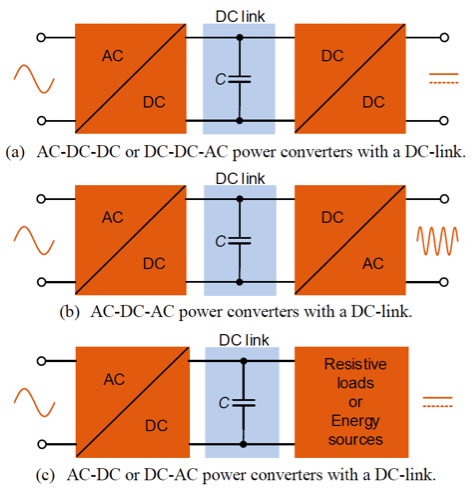
DC link capacitors are commonly used in power converters as an intermediary buffer between an input source to an output load that have different instantaneous power, voltages, and frequencies. In electric vehicle (EV) applications, DC link capacitors help offset the effects of inductance in inverters, motor controllers, and battery systems. They also serve as filters that protect EV subsystems from voltage spikes, surges, and electromagnetic interference (EMI).

Figure 1. Common uses for DC link capacitors in power conversion systems (source: Center of Reliable Power Electronics)
Take a look at the on-board charger (OBC) in Figure 2, which is responsible for charging the traction battery. Inside the OBC resides:
- The AC/DC converter that converts alternating current (AC) from electric grid into direct current (DC) using rectification and Power Factor Correction (PFC)
- An intermediate DC link circuit for energy buffering
- The next stage DC/DC converter that adjusts the produced DC voltage to provide correct DC levels to the battery.

Figure 2. Simplified block schematic for AC/DC stage of OBC
The DC link capacitor Cbulk is placed between the rectifier and DC/DC converter. Desired characteristics for the capacitor include:
- High DC voltage rating: 300V to 500V
- Very large capacitance: 200µF to 1500µF
- Operating temperature range: -40°C to +250°C
- Low equivalent series resistance (ESR): < 1.5mΩ
- High root mean square (RMS) current capacity
- High mechanical ruggedness
To meet the large capacitance values, multiple capacitors or a capacitor array is required. We recommend using our high-capacitance StackiCap 1812-4040 250V-1.2kV 100nF-5.6µF X7R capacitors for such applications. The DC link capacitor must be also able to handle twice the line frequency. Therefore, common circuit arrangements include multilayer ceramic capacitors (MLCCs) connected in parallel with other capacitor technologies to achieve this.
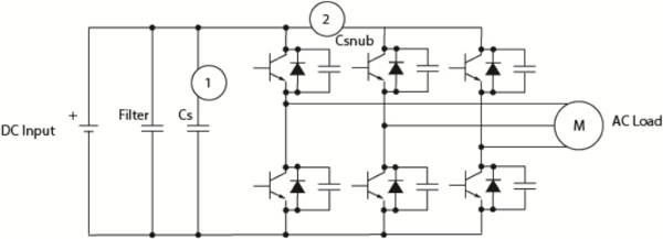
Another EV subsystem where DC link capacitors are found is the inverter in motor drive circuits (shown in Figure 3). The inverter converts DC power from the battery to three-phase AC power to drive the traction motors during acceleration, and then converts AC power back to DC during braking. It also detects the motor’s speed and position and drives the insulated-gate bipolar transistor (IGBT) power stages.

Figure 3. Simplified block schematic for inverter in motor driver circuit
In this subsystem, the DC link or smoothing capacitor Cs is placed in parallel between the DC (battery) and the AC (load) sides of the voltage inverter. The capacitor specifications are very similar to the previous OBC example, and therefore the same StackiCap X7R with high RMS current capacity is recommended. Due to the high capacitance requirements, small-sized MLCCs can be used together with film and aluminum electrolytic capacitors to integrate closer to the IGBT switching device and improve high frequency attenuation.
Given the high number of converters and inverters found in EV applications, selecting the right high-voltage, high-capacitance DC link capacitor is of great importance to the overall system success. For more information, contact us to discuss your specific use case, or read our white paper Considerations for Selecting Automotive-Grade Multilayer Ceramic Capacitors in Electric Vehicles.


